Permanent Magnetic Couplings
Permanent magnetic coupling (PMC) is a transmission device that uses permanent magnets to transfer torque or power between two shafts without direct mechanical contact. This form of magnetic coupling relies on the attractive and repulsive forces between the permanent magnets to synchronize the motion of the two coupled components.
Principle of Permanent Magnetic Couplings
Permanent magnetic couplings usually consist of two rotors. One of the rotors is connected to the drive motor or input shaft, while the other rotor is connected to the load or output shaft. Strong permanent magnets (e.g. neodymium magnets, samarium cobalt magnets) are embedded or mounted on each rotor. These magnets are arranged in a specific pattern to optimize torque transmission.
The magnets are typically arranged in alternating polarity (north-south-north-south). As one pole moves past an opposite pole, an attractive or repulsive force is generated, which causes the driven rotor to rotate in synchronization with the driving rotor. Due to the interaction of magnetic fields between the permanent magnets in the rotors, when one rotor turns, it induces motion in the second rotor, thus transmitting torque.
Benefits of Permanent Magnetic Couplings
- Slip: One of the unique features of PMCs is their ability to “slip” under overload conditions. When the load on the driven side exceeds a certain threshold, the coupling can slip without causing damage. This inherent slip makes PMCs useful as torque limiters or safety couplings, protecting machines from overload damage.
- No Contact, No Wear: The biggest advantage of PMCs is that they operate without physical contact between the two shafts. This eliminates friction, reduces wear, and minimizes the need for lubrication.
- Seal-Less Systems: In applications such as fluid pumps or mixers, PMCs can be used to create seal-less systems where the driving motor is isolated from the fluid. This prevents contamination and eliminate

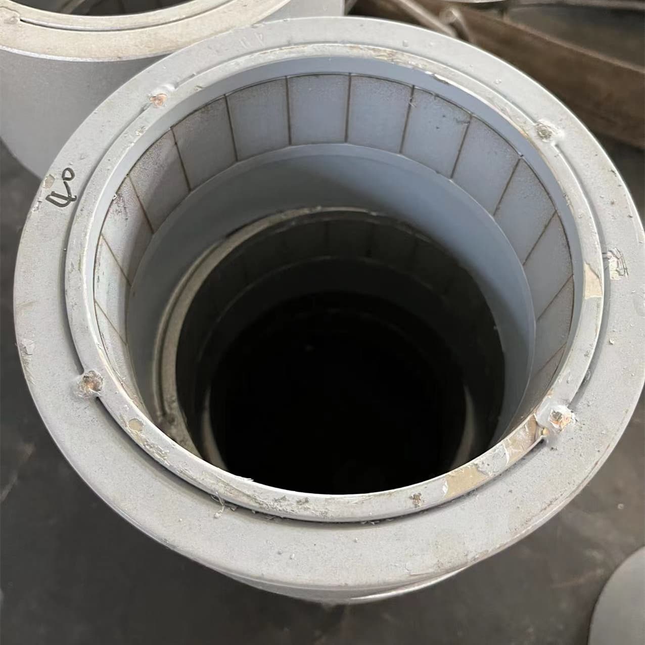
The external rotors of the axial permanent magnet coupling in our assembly workshop
How to design permanent magnet couplings? Factors that determine the torque of permanent magnet couplings
1. Magnetic Strength (Magnet Material and Size)
The torque transmitted by the permanent magnet coupling is directly affected by the material of the permanent magnet used. The strength of the magnet is usually measured by its remanence (residual flux density) and coercivity (resistance to demagnetization). The magnets commonly used in permanent magnet couplings are Neodymium magnets and Samarium Cobalt magnets. Some special permanent magnet couplings also use AlNiCo magnets. In terms of shape, the magnets are usually designed to be trapezoidal, arc-shaped, square, etc., depending on the type and shape of the rotor.
2. Number of Magnet Poles
The number of magnetic poles (north and south) in each rotor significantly affects the torque capacity. More poles create a stronger and more distributed magnetic field interaction, improving the coupling’s ability to transmit torque. However, increasing the number of poles can also make the system more sensitive to alignment and speed variations.
Higher Pole Count: A higher number of poles increases the torque density because it distributes the magnetic forces more evenly over the surface of the coupling
3. Magnetic Coupling Distance (Air Gap)
The air gap, or the distance between the two sets of magnets on the driver and driven rotors, is a critical factor that determines the strength of the magnetic interaction and, therefore, the torque that can be transmitted.
Smaller Air Gap: A smaller air gap results in a stronger magnetic field interaction between the two sets of magnets, allowing for more torque to be transmitted. However, if the gap is too small, it can lead to practical issues like friction or misalignment problems.
Larger Air Gap: Increasing the air gap reduces the magnetic flux that links the driver and driven rotors, which decreases the maximum torque the coupling can transmit. In some cases, this is necessary to avoid physical contact or for isolation, but it comes at the cost of lower torque capacity.
4. Types of permanent magnetic couplings
The direction of the magnets on the rotor (e.g. axial or radial) greatly affects the efficiency of torque transmission.
There are generally two types of permanent magnetic couplings, axial permanent magnetic couplings and radial permanent magnetic couplings. These two types of permanent magnetic couplings have completely different torque transmission efficiencies.
Axial couplings, also called magnetic pumps. It usually consists of an inner rotor and an outer rotor. Usually the outer rotor is connected to the motor to drive the inner rotor to rotate. After the inner and outer rotors are assembled, they are shaped like two cylinders, and the permanent magnets in the cylinders interact with each other to produce synchronous rotation.
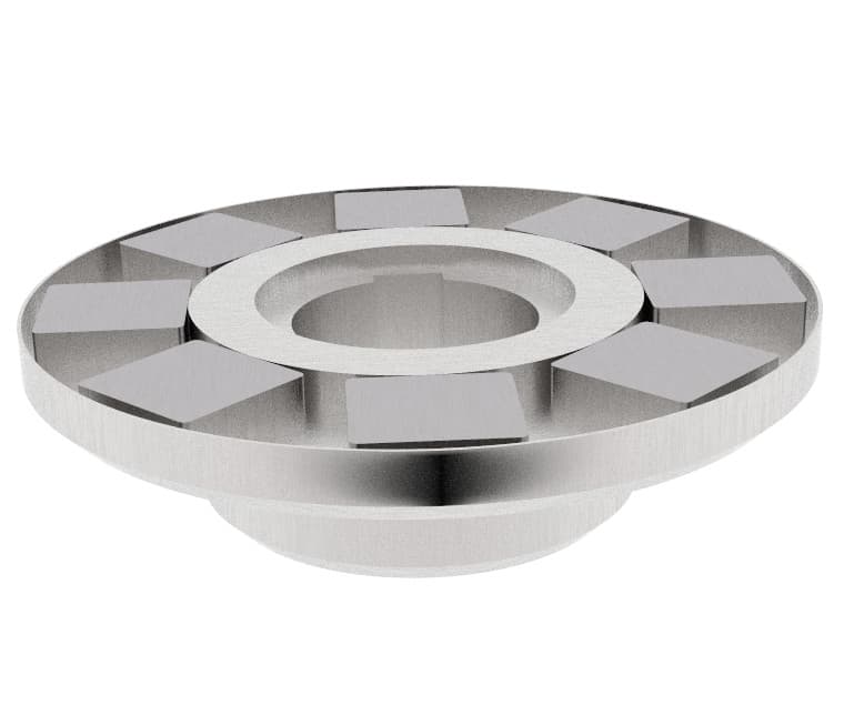
Radial couplings: Magnets are arranged around the circumference of the rotor, allowing radial torque transmission. They are usually disc-shaped, with magnets embedded in the disc, and the rotation is generated by the interaction of the permanent magnets in the disc.

Radial disc permanent magnet coupling
5. Magnetic Saturation of the Material
In some cases, the magnetic core material of the coupling can reach magnetic saturation when exposed to very strong magnetic fields. Once saturation occurs, the material cannot carry any additional magnetic flux, which limits the maximum torque that can be transmitted.
Magnetic Core Saturation: If a ferromagnetic material is used between the two sets of magnets, it can become saturated at high field strengths, reducing the effectiveness of torque transmission.
Material Selection: Materials with higher magnetic saturation points (such as ferrites or certain steels) are preferred in high-torque applications to prevent premature saturation.
6. Speed of Rotation (Frequency of Magnetic Field Interaction)
The rotational speed of the driver rotor relative to the driven rotor can influence the performance of a PMC, particularly when operating at high speeds.
Low Speed: At low speeds, the coupling is typically stable, with minimal slip. The torque transmission depends largely on the magnetic field strength and the alignment of the rotors.
High Speed: At higher rotational speeds, effects like eddy currents and hysteresis losses in the magnets or any conducting materials near the magnetic field can reduce the coupling’s efficiency, lowering the torque transmission. In some cases, excessive speed can lead to magnetic slip if the magnetic forces are insufficient to keep the rotors synchronized.
7. Eddy Currents and Losses in Conductive Materials
If any conductive materials (e.g., metal barriers, surrounding equipment) are placed near the magnets in a PMC, eddy currents can be induced in these materials due to the changing magnetic field as the rotors move.
Eddy Current Losses: These circulating currents create resistive losses, generating heat and reducing the magnetic field strength available for torque transmission. To minimize eddy currents, materials with low electrical conductivity (such as stainless steel or non-metallic composites) are often used as barriers between the magnets and the environment.
Hysteresis Losses: Similar to eddy currents, hysteresis losses occur in the magnetic material itself due to the continuous reversal of magnetic domains. This effect becomes significant at high speeds and can reduce the effective torque output.
8. Operating temperature
The temperature of the PMC’s operating environment plays a key role in determining its torque capacity. Permanent magnets, especially neodymium magnets, will lose or even lose their magnetic force as the temperature rises. Neodymium magnets usually have operating temperature regulations. When designing couplings, it is necessary to properly select the grade of neodymium magnets for the appropriate temperature. In high temperature environments, using materials with better temperature resistance (such as samarium cobalt magnets) can help maintain torque capacity in high temperature environments.
